Sunday, 12 April 2015

Robot No.2 Always at the ready


This is my second robot model based on the Ashley Wood pictures and using that stainless steel cistern float thingy I mentioned in the last entry. He sort of looks like he is at the ready, twitchy fingers, staring eye and all, so that's his moniker from now on.


Finally we get to see the steel float which has always looked like a potential robot to me, and together with the rusty gas tank I saw in Adelaide, I was destined to build a few metal men.


I made a mould of the float and cast various forms, the top pic being the one for this robot. The way the raised seam line came out was pleasing and gives some immediate character to the piece. A cast cylinder was ground down and glued to a plastic base plate with some other cast bits stuck on for good measure (the first of many).


Arms and legs make the model and I wanted the same basic form to do both jobs.This shows the master for the arm/leg piece together with the hands, a right and a left. Maybe later I will work out a way to use a single piece but at this stage I think the hands are so important at a detail level at least. I made another mould for the limbs as I would need eight in total and you can see that the half check built into the master allows two pieces to be joined as an elbow or a knee.


The fingers can be made many different ways and I have tried a few - all of them drive me crazy. This method where 3mm plastic is ruled up and a male/female system of grooves is sawed and filed, seemed to give enough basically equal sized joint segments for two four fingered hands. The file at the top was sharp enough to cut the female side while a razor saw dealt with the protruding male lug. That little soft jawed vice from Games Workshop has been invaluable. The bottom shot shows how the forearm casting has been cut off at the wrist and joined to the hand with a brass tube augmented with a wire connection. As the hands are separate, right and left, they have bulges that orientate the thumbs differently from the fingers creating a hand that may be able to grasp a tool realistically.


One of the main things I wanted this robot to have was some panel lines and to do this marking I needed a very hard, not necessarily super sharp, tool. My engineering friend had just the thing, a needle from a rust removal tool and allied with templates used in rescribing panel lines on plastic aeroplane kits, I set forth with a bit of trepidation. Resin is quite hard and therefore slippery and to scribe a good round corner without skidding past where you want to stop is tricky. I feel happy with the result but there aren't many on this robot, maybe I'll be more ambitious on the next.
Just cutting the groove around the top took a bit of planning and a lot of gentle sawing in a temporary jig.
The middle pic shows the tools used to scribe and finish the lines and grooves, a hobby knife, a dental tool and the hard sharp needle.
At the bottom is the robot laid out with arms and legs where they will end up.


Another side on photo I'm sorry but an important one. All my models are accompanied by pages of plans in my sketch books and this shows the thoughts behind the weapon that the robot will carry.
It is similar to a grease gun affair that an Ashley Wood robot held but mine was based on three cylinders combined for the major part with a flamer barrel and a more elaborate handle. Also on this page is the plan for his feet which I changed by using a casting previously made.


.
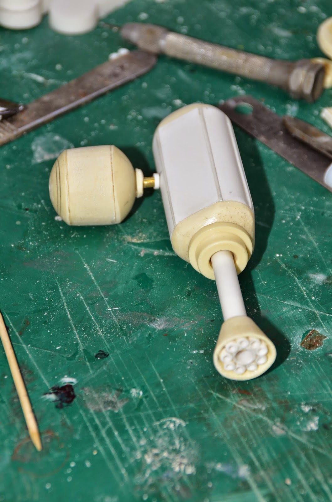
These pictures show the stages in the making of the weapon and all the resin bit are cream while the white is plastic.The bands are copper and a brass rod strengthens the whole length of the thing.


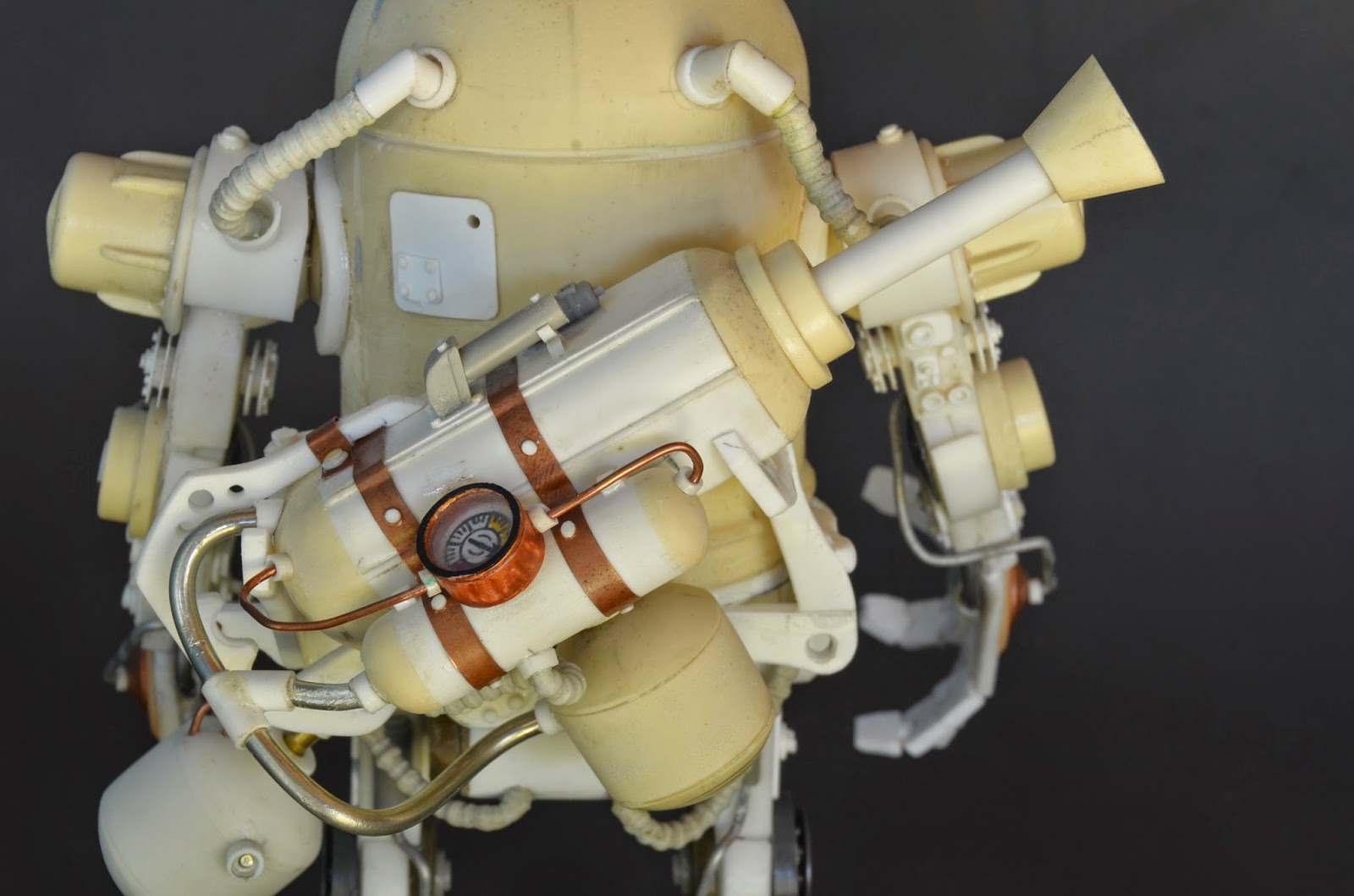
And there he is, unpainted in all his fiddly glory. There are little bits of kit parts, cut plastic sheet, resin castings (especially at the joints), wires, tubes, brass bits,solder bits, anespecially tricky scratch built pressure dial and some homemade braided lines. I saw the "tentacle maker" that Games Workshop sells and decided to make my own, not too sophisticated but sort of useful. I particularly like his flamer and decided to provide him with a spare fuel canister hanging from his weapon rack.
 
 
This is what he looks like without the gun and building the rack to fit was one of the trickier parts of the project but also one of the most satisfying as it is crazily asymmetric and suits such a character.


The finished product resplendent in a hairspray blotched paint job. This is a paint technique where after a base colour is applied then sealed with a lacquer varnish, a layer of hairspray follows.Over the hairspray the top colour is laid and,being acrylic, is susceptible to water damage. That is exactly what we want, for by wetting the barely dry top coat, it can be removed with a toothbrush to allow the sealed base coat to show through. If your base coat were rust coloured then this is the colour that will be seen in all the areas where the toothbrush had removed the top coat.A clever technique which can be manipulated by varying the order of colours and the time of drying between stages. 
 
I enjoyed this build and have put the two robot images on my board "Things I have made" on Pinterest.


Friday, 10 April 2015

Making Robots No.1 They told me to wait


This is what I saw as I was walking to the golf shop in Adelaide carrying my camera and looking for interesting things. Well I could see an Ashley Wood robot there for the making and that is what possessed me to move away from sculpting figures, to enter the realm of assembling stuff. I hoped it would be more straight forward, would allow the greater use of cast objects and perhaps be able to make use of the plethora of plastic kits that have accumulated over the years. Kitbashing here I come!


You can see it can't you? That old tank is crying out for a new life as an equally old, sad neglected robot that everyone forgot.


And here it is. The title in my album is, "They told me to wait" and  that about sums up this poor bot's fate because it's destined to sit on that pier until it or the pier rots. When this was made very few photos were taken of the build, I think we were in the middle of a monsoon and I don't like to take my camera out of its dry box in that type of weather. Subsequent robots get a better deal than this sad chappie.


To get to the stage of assembling the piece I had to make or find the shapes that would do the job. The top pic is a panel of things I found in my workshop which were cast in resin and stored in convenient trays . This is one of many such groups of objects of basically the same size that could be cast and stored. Simple shapes such as cylinders and spheres of various sizes are essential in the types of figures I would be making and selective casting in partial moulds gives greater variety still.


As I said before,this build was not well documented but a few pics were taken. The top one is a smoothing and rounding of a cast sphere using a drill and the other is a way of using all those older moulds of zombies I had lying around. It takes quite a bit of work cutting up the silicon moulds before they can be fed into an old fashioned meat mincer, but once reduced to a small grain size, the silicon can be mixed with fresh stuff to bulk out future moulds. A thin layer of new silicon is poured into the mould box all over the master, thoroughly coating it and then a second thicker coat, augmented with the old cut up moulds, is added to the first coat thus giving the necessary thickness without having to use completely new silicon all the time. It saves a bit of a quite expensive product and works very well.


Final pictures of the robot undercoated sitting on the scratch built pier then a series of finished shots from various angles. The last is of a blue starfish living in the water under the pier and of the oysters that have grown on the rusting pier supports. 


Monday, 19 January 2015

Ork Racer Part2


This entry is all about the building of the racers themselves.As was mentioned in the previous entry, I  used two spare tank turrets from Trumpeter kits for the bodies of the vehicles, but they needed a good deal of modification before use by Orks. The one on the right is unchanged except for a layer of kit armour, while that on the left has been drilled, hollowed  and fitted out with a rough cockpit and a much larger gun.


All grey parts are original kit, while white is the colour of sheet styrene. The shape of the cockpit is neither here nor there at this stage, as the actual driver will determine the final look of this aspect of the build.


One overriding factor governs these types of build and that is, "leave no surface untouched". I really wanted to see a big bulging differential hump on these buggies, so it had to be made. Apart from the wheels this would be a cast item (Ike's brief). Here we see the black plastic master, the pink silicon mould and the final casting. At this point the second cast has not been removed.


Each vehicle needed a ventral structure to complete its chassis and they were made with simple boxed forms from styrene. This plastic sheet is the perfect modelling material in that it is made in various thicknesses, can be cut by scoring and snapping, glues using a solvent or super glue and takes paint well, either acrylic or enamel. On the left you can see a piece of Evergreen styrene L beam which has been used to reinforce the edges of the box. Evergreen makes such extrusions in many useful shapes including tubes, rods, U forms, I beams, flats and sheets.
 

Now the fun starts, cluttering up the surfaces with whatever you can think of. Here I can see electronic items, lead solder, kit parts, that resin diff, lead sheet, a cut styrene Ork symbol and many, many rivets cut from styrene rod.


Each vehicle represents a similar buggy type but owned by two different Ork clans. This being the case they have to be individually outfitted. On the right is a high rider of the Blood Axe clan while the other is a low rider of the Bad Moons.

 
 I always detail the undersides even though they may be invisible once the final placement is made.


Here can be see the cast hemispheres used as hubs for the low rider's wheels. They had to ground to fit the space but really they weren't planned at all. I had originally decided to have a differential hump, but found that there really wasn't enough room and so they became these groovy wheel supports. The fuel tanks were tubes cut and fitted with circles made with a cheap punch kit.


This is the Bad Moons low rider almost complete before painting. There is a bit of work to be done on the upper surface  when the driver makes his entrance. I am particularly pleased with the exhausts and the use of some great stainless steel swarf (curled debris from lathe work). This was used as hydraulic lines feeding the complex front ends. 


And here is the Blood Axe high rider complete with already red painted missiles. As cast parts are cream in colour, you can see that I have used a previously made  fuel drum on this buggy which gives it a different look from the other.


Both together and awaiting their drivers and a paint job.