This entry is all about the building of the racers themselves.As was mentioned in the previous entry, I used two spare tank turrets from Trumpeter kits for the bodies of the vehicles, but they needed a good deal of modification before use by Orks. The one on the right is unchanged except for a layer of kit armour, while that on the left has been drilled, hollowed and fitted out with a rough cockpit and a much larger gun.

All grey parts are original kit, while white is the colour of sheet styrene. The shape of the cockpit is neither here nor there at this stage, as the actual driver will determine the final look of this aspect of the build.

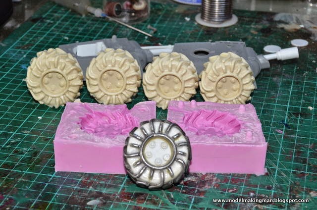
One overriding factor governs these types of build and that is, "leave no surface untouched". I really wanted to see a big bulging differential hump on these buggies, so it had to be made. Apart from the wheels this would be a cast item (Ike's brief). Here we see the black plastic master, the pink silicon mould and the final casting. At this point the second cast has not been removed.

Each vehicle needed a ventral structure to complete its chassis and they were made with simple boxed forms from styrene. This plastic sheet is the perfect modelling material in that it is made in various thicknesses, can be cut by scoring and snapping, glues using a solvent or super glue and takes paint well, either acrylic or enamel. On the left you can see a piece of Evergreen styrene L beam which has been used to reinforce the edges of the box. Evergreen makes such extrusions in many useful shapes including tubes, rods, U forms, I beams, flats and sheets.

Now the fun starts, cluttering up the surfaces with whatever you can think of. Here I can see electronic items, lead solder, kit parts, that resin diff, lead sheet, a cut styrene Ork symbol and many, many rivets cut from styrene rod.

Each vehicle represents a similar buggy type but owned by two different Ork clans. This being the case they have to be individually outfitted. On the right is a high rider of the Blood Axe clan while the other is a low rider of the Bad Moons.


Here can be see the cast hemispheres used as hubs for the low rider's wheels. They had to ground to fit the space but really they weren't planned at all. I had originally decided to have a differential hump, but found that there really wasn't enough room and so they became these groovy wheel supports. The fuel tanks were tubes cut and fitted with circles made with a cheap punch kit.


This is the Bad Moons low rider almost complete before painting. There is a bit of work to be done on the upper surface when the driver makes his entrance. I am particularly pleased with the exhausts and the use of some great stainless steel swarf (curled debris from lathe work). This was used as hydraulic lines feeding the complex front ends.


And here is the Blood Axe high rider complete with already red painted missiles. As cast parts are cream in colour, you can see that I have used a previously made fuel drum on this buggy which gives it a different look from the other.

Both together and awaiting their drivers and a paint job.