Monday, 3 June 2013

Modelling Typhus Part 5 - Daemons on the left, Skulls down below


 There aren't many classic illustrations of our friend Typhus, Herald of Nurgle, but these two keep popping up in reference to him. The left pauldron, in these cases, shows an open mouthed daemonic head. (In the Warhammer world, yes there is an an extra 'a'). On the official Games Workshop miniature of Typhus, the emblem on the left shoulder is a giant fly, Nurgle's favourite carrier of disease, but I had enough of flies during the Korpus Festerheart build and so it was the daemon for me.


I started with the problem area first, the open mouth, seen in the illustrations as a blank blackness. What to do? I did have a fall back device though, the hive structure I had used to gap fill on the main body. This was joined to the lower jaw and we were away. The daemon had a central nasal horn and two large curved fangs in the lower jaw. These were all made of Apoxie Sculpt, cured separately in the turbo oven and scored with a sharp tool to give a bony, horn like appearance. The toothpicks were inserted to make the handling and heating processes easier.


The large upper jaw needed to be made of putty as well as all the other bits, but the Apoxie  I use for general modelling takes too long to cure to hold this hollowed shape. Kneadit to the rescue! This stuff goes off so quickly that I was able to form the shape roughly, attach it to the pauldron top and keep the gap open, all in about two minutes. Within ten minutes I could use a motor tool to grind away any imperfections and have it ready to be worked upon with the detailing putty- great stuff.


I had recently bought this Dremel bit and now had found a perfect job for it. The fangs needed a good strong attachment and by grinding the base down to a smaller peg, (easily done with such a nice square tool), they were able to be housed in the jaw in a secure but small hole. I don't like gluing things together without some sort of connective piece, be it a pin of wire or in this case, a peg.


In they go. I probably shouldn't have glued them  at this stage as it would have made the teeth fitting a bit easier but there you are, you can't get it right all the time.  I think the question came up as to glue or not to glue, but ' what the heck' won and so the teeth went in later.
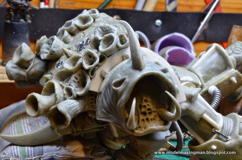


Here we see the modelling of the top of the head with the horn in place, eye sockets and a bit of skin fold detail started. It looks sort of benign and frog- like at this stage, even with those fangs. I'm sure such niceness can be eliminated with a few teeth.
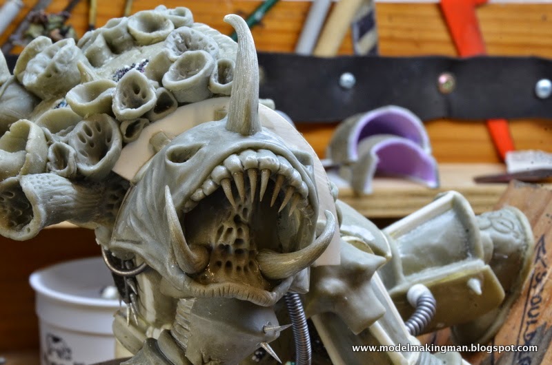

The teeth were made of Apoxie which had been rolled into a number of equal sized balls. Each small ball was then rolled into a cylinder and each end of the cylinder was rolled into a taper.These twin sharp ended shapes (like spindles) were then slightly curved into a bow. I now had quite a number of potential teeth, all I had to do was cure them in the turbo oven (10 min. @ 140 degrees C.) Once they were cool, I cut each bow shape and voila, two nice pointed teeth. This process gave me a choice of many teeth and I was able to match them to each other and their position in the jaws. They needed gums to be set into and I think animals that show their gums and teeth when angry are the fiercest looking, so this guy really got  a set of humungus gums.


All the teeth in and what a pretty smile he has. A face only a mother could love but then again, this bugger probably ate his mother, warts and all.
The eyes are those jewellery/ pearl things I used for the torso signals buttons or whatever they were.
A difference you'll notice between the two preceding pics, is that the areas at the front and back bases of the shoulder guard have modelling done to them.


These areas seemed to need something and even though the illustrations don't show much, I was able to fit in an arm at the front, and a tentacle at the back. I'm quite pleased with the arm, as it seems to be hanging on for dear life, whereas the tentacle just wants to keep away from that mouth.


On the right pauldron, the miniature has the typical Nurgle arrangement of three skulls. I decided to put three 'skullish' type things, a zombie head, ghoulish head and, yes, a skull. These looked a little lonely so I added some putty spikes as well. The curve in the spikes looks especially nasty and definitely discourages any nurgling trying to climb up Uncle Typhus' arm.


Speaking of skulls, here is the mould for making them. I thought I would need a few for the base so made another to speed up the process. One of the skulls was drilled out to take a chain and become that detail seen in the top illustration( but not on the miniature).


Here it is in place attached by pustulated bits of armour, all hived out as usual


This is a shot of the cast skulls ready to be undercoated in my spray booth. I could have shown them after that operation but you wouldn't have seen them against the general blackness of the booth.


(A)

(B)


Here they are - (A)  Mounted on cottonbuds (skewers were not thick enough for the holes I had made with  extra drilling and individualising of each) and painted with Citadel Bleached Bone.
(B) Washed with a mixture of Brown ink, Chestnut ink and Agrax Earthshade.


Well, Typhus the model is finished, now begins the painting and basing. That's an entry for next time.

(Note how long his right arm is. I did and was not well pleased. Some radical surgery was in order - drastic at this stage of a project, but necessary and do-able)


Friday, 31 May 2013

Modelling Typhus Part 4 - Chest detail, Cabling and Hands


This chest area has had a number of different treatments, mainly due to its curvature and size, but the addition of the front cables was the most radical. The size of the central unit was such that if it were placed on the surface, it would protrude too much, so I decided to excavate an area for it to be dropped into the chest. Various Dremel tool tips allowed the job to be done fairly neatly and even though it looks quite painful, no monsters were harmed in the fabrication of this area.

 
 The central unit was a complex little piece in that the tubes on either side had to be slightly curved to conform with the rounded chest, and this was achieved by gently heating the tube in a candle flame. Tube does not like this treatment and care must be taken so as not to kink it. The whole of the plastic assembly was mounted on heavy solder as this allows any bending with ease. Kneadit, (a quick curing two part plumber's putty), was used to make the large fluted centre piece, as it gets very hard, very quickly and can be drilled and sanded within ten minutes. I had to make a couple of these because my initial triple grooves were a bit wonky. Evergreen styrene tubes are designed to fit into each other as the sizes increase, and as I have a good supply of them, all manner of mechanical joints can be manufactured. Love the stuff!


These pics show the placement and filling work needed to get the unit seated in the chest. Where the cables enter the body, the junction was made with Apoxie Sculpt as even Evergreen does not have such a shape. The cables themselves were made by wrapping thin solder around the thick and making sure they were tight enough so that they would hold a bend without exposing too much inner wire.

 
Here is the three-way junction under the right arm, made of putty and fitted tubes, ready to accept cables from the belly and right shoulder. Gluing the pieces into position was not necessary as the curing putty does the job by itself.


General overview pictures of the cabling in place as well as details of the typical Nurgle bloated and rotting belly, complete with pustules so large they look like eggs.
Other features include chain mail made from lengths of jeweller's chain hung in super glued parallel rows, collar spikes added to the gorget around the head casket and strange hip pieces that all 'space marine' type figures have.
I have added rivets (made from slices of plastic rod), to any piece of piping to show the mechanical aspect of these super warriors, as well as smaller cables connecting upper leg to the knee joint.


Two succeeding pics of the left side, showing the treatment of the space between the body and arm which gave me a bit of a headache earlier in the build. Putty was added in a layer to cover the smooth plastic surface and then more was added in various places to build my preferred, 'hive' structures. I alluded to using these when there was a space to fill, but only with an appropriate structure. I think that the 'hives' fit the bill.


Here is a good overview picture of the figure showing the left hand gripping the weapon and subsequently, the whole idea of the Typhus model. In this can be seen the 'hive' structures doing their job of appropriately filling the gaps under the arms.


Three views of the left hand in the process of gaining its armour. Thin lead sheet was cut individually to fit each finger and to link the top plate to the lower. A cutting wheel on the motor tool was used to abrade the edges of each piece to denote battle damage and general wear.


Here are similar shots of the right hand showing the rivet detail on the hand armour as well as some closer  details of the weapon. It had the same 'hive' treatment as the main body but with a little subtler use. In these pictures can be seen the 'wood' treatment of the haft of the Manreaper and those parallel marks, indicating timber, were made in the putty covering with that silicon tipped tool I had mentioned earlier. The black hemispheres, representing large rivets, are found in the scrapbooking or jewellery departments of craft shops or cheap outlet stores. They come in a range of sizes on a plastic sheet and have a low tack adhesive on the back. I chose black ones but pretty pink would have done just as well.


 To finish this entry we see the whole model with the weapon undercoated in Games Workshop Chaos Black spray paint. You can see how big this scythe is and how it presents a problem in posing any converted version of the original figure. My model, just by being as large as it is, has I think enough impact that a simple lowering of the right arm is a sufficient diversion from the original to be acceptable.


In the next entry I will cover the modelling of a different and spectacular daemonic left pauldron, as well as possible plans for the display base  and maybe some ideas on painting the monstrosity in oils.


Tuesday, 28 May 2013

Modelling Typhus Part3 -Torso & Arms


Typhus, being a champion of the chaos god of disease, Nurgle, shows his fealty to his lord by carrying a virtual hive of pestilence on his back in the form of these open funnels. I had to do some serious cutting and grinding to remove enough plastic from the top edges of the box-like torso, to allow the putty funnels entry. They initially were difficult to form and handle in the soft putty but after a few goes, the process sorted itself out.

  
At first the funnels were made as singles, but as the putty hardened, I found it was easier and more interesting to make them as doubles or even triples. A largish piece of putty was rolled into a rough solid cone, inserted into a single funnel, then hollowed out and formed with a wooden pointed tool. Once in place it was much easier to form the lip, any curves and texturize the whole new funnel. This is a characteristic of working with putty, in that it needs some sort of stability, be it attachment to a base or given enough time, the stability of curing.


As per the original miniature, the whole top of the backpack had to show the rotten ravages of Nurgle. It was an easy job to incorporate those trusty micro balls as pustules as well as erupting spines and various holes, scars and general rot. A favourite tool of mine for this type of surface texturing is a silicon tipped 'paint' brush. This is great for inserting at an angle to form an off- centre hole, perfect for the entry or exit of a disease carrying grub or maggot. Yum!

 
 Here we see the doubled up funnels and a clearer view of the surface damage.
Just below can be seen the three large 'hive' bulges which are characteristic of this model. Remember that the symbol of this god is a cluster of three rounded things, be they circles, skulls or dead faces.


The rear view of Typhus' backpack has those circles plus more rotten armour and two special cone centred bulges which form part of the under arm connection detail. This was an area where the miniature wasn't really helpful because it was just so difficult to figure out what I was looking at. Really you shouldn't worry too much about problems like that - I mean, who else is going to pick you up on whether Typhus' armpit didn't look like that? My solution was to find a suitable detail form and bung them anywhere there seemed to be a gap. I chose a raised patch of diseased armour and riddled it with maggot holes - space problem solved!


Again with the combination of finished parts. This is getting ready for the arms and that underarm problem is starting to come to the fore. The arms have to fit not only the proportions of the figure as a whole, but they must be positioned in such a way as to fit the already made weapon. Hands do not hold weapons, the weapon has the hands attached to it. I had to make the arms, always with the distance apart and above the ground in mind, especially this weapon which is physically much taller than the whole figure. Because the attachment points of the hands on the weapon are fixed, the end points of the  wrists had to be a specific distance apart and so the question of underarm angles and included detail burns brightly.


pic 5


Here is a sequence that shows the Push Forming of the pauldrons or shoulder guards.
Pic 1   The tools required - plastic sheet  held in place over a hole in a piece of ply, hot air gun, the steel round ended master to be pushed into the plastic once heated.
Pic 2   After the push, seen from the lower side.
Pic 3   The regular view with the damage done.
Pic 4   The form removed but not yet trimmed and a sheet of putty, dusted with powder and rolled out ready to cover the shoulder guard once cut. Powder stops the roller from sticking to the putty.
Pic 5   The form was cut in half to make two curved shoulderguards. Here is one, covered in its layer of putty.
Pic 6   Two pauldrons, complete with curved inner 'fences' and fitted next to the torso.


What's this? Two purple pauldrons? On fitting the push formed white pair to the figure, I decided they were too big for the arms I was in the process of making, so the search began for something that would be a better fit. I didn't go the push form route this time as the master needed to be smaller and I just didn't have such a master that was heat proof. I did find however, a deodorant top (purple), which seemed to fit the bill. Great! So I went ahead and covered these halves with putty, fitted them to the figure only to find that they were too small! Thank goodness I didn't go to the trouble of 'fencing' them before I found a solution.
 

There is a considerable size difference isn't there? Two solutions - one easy, one more difficult. Cut the big one and remove a section, rather than cut the smalls and add a filler piece. Piece of cake!

 
 It seems that I did put the backing 'fence' on the smaller ones after all - forgot that. Well they'll  do for a space marine figure if ever I get the urge to go there in the future.
The first large one and the same, with a section removed are seen here on either side of the little purple job.


Here are the final sized pauldrons, slightly pointed at the top with all joints shimmed together and ready to go.

This is the starting process in making an arm, in that is a piece of wire being bulked up with aluminium foil. That is standard practice for most putty covered models, but the interesting thing about this photo is where the work is being done and to a lesser degree, the way I have found to work the foil. Apart from an article in Fine Scale Modeler (Maximo Salas on modelling dinosaurs), all the techniques I use have been self taught. Necessity has been the instigator of the way I work as I do not have anybody to bounce ideas off - no clubs, no modellers  and when I started, no internet. I needed a bulging piece of foil at the top of the arm to fit inside the pauldron and it needed to be flat on one side. By drilling holes in my temporary bench, I was able to position the piece and using a small hammer, pound the foil into shape, very tightly. This precise shaping of the underlying foil allows the top coat of putty to be thinner - a saving in putty use, not only in amount used but in curing time. Those holes, on the sides as well as the top surface, have been in use for any process involving wire where a bit of stability is needed.


He looks like something now, even with a rudimentary arm, doesn't he? The foil was twisted then wrapped tightly to give a good 'tooth' for the putty to adhere to. It wasn't measured as such because any adjustments could be easily made at a later stage, however, when test fitting the pauldron, I found my enthusiastic funnel building had encroached into the pauldron's fence. (I really should find out the proper name for that raised arch of armour that backs the shoulder guard).
Some heavy grinding took place and the area in question was relieved. This too can be fixed at a later date with part funnels being sculpted where needed.

 
More arm work here with the under pauldron support piece sculpted. This posed a problem as it is very hard to see how these underlying structures are shaped. The fact that they are partly visible means that the making of them requires some thought.

Pic A

Pic B

Pic C

Pic D

These last four pic's show various stages in the modelling of both arms.
Pic A   Here we see the elbow armour formed, a difficult piece requiring full curing, followed by grinding to shape. The ribbed joint structure is formed and you will note that some of the belly detail and chest cabling is also present. These details will be discussed in the next entry, but needed to be done before the arms/weapon/hands unit was attached. How small is that little guy?
Pic B   The forearm piece (vambrace?) is added with its complement of Nurgly nastiness.
Pic C   The right arm was much faster to model once the lessons were learnt on the left. BUT - a problem showed its ugly head way at the end which required some drastic intervention. More about that later.
Pic D   This is a critical picture concerning the relationship of the arms to the holding of the weapon. Where and how to model the hands - hands being only second in importance to the head. Rubbish hands, rubbish figure.

Next entry, chest and belly detail, cabling and hands.