Tuesday, 21 May 2013

Modelling Typhus, Herald of Nurgle Part1 - Plans, Torso, Head


This is the Games Workshop miniature of Typhus, Herald of Nurgle. A repellant figure, but similar enough in pose and form to the last large scratch built figure I built, Korpus Festerheart. I felt they'd make a good pair in my showcase and, even though the builds would necessarily be similar, their origins, (one from a painting, the other from an existing miniature), would ensure different problems in their realisation to a final large, spectacular model.


I started out in my usual method of drawing a squared up plan, in this case based on the dimensions of an existing model, but found it was easier to use that model's dimensions and multiply them by a factor of 5. This gave me a total height of approximately 200mm.


Now most large "additive" sculpts are built by adding material onto a supportive structure or armature. I build my armatures from soldered galvanised wire and this really sets up the action in the figure, how it is seen to be about to move, before it is frozen in time. Because Typhus uses a giant scythe (called Manreaper by the way), I felt that it would be held low in the right hand to deliver a more sweeping blow, not the downward chopping action of an axe. Also, this scythe is HUGE, much larger than Festerheart's axe, so the act of getting it to swing would take a lot of body motion and so I worked on a golfer's downswing, where the hips are turned before the shoulders come into play. The starting wire work seen here shows differing angles of hips and shoulders BUT things just did not work out that way.
 

I really enjoy soldering and think that I can build anything just with wire. Wrong! Here we see the wire armature, hips turned 45degrees to the shoulders etc etc, but this did not allow the plastic parts, especially the bulky, boxy torso that all Space Marine terminators have, (see the real sized grey plastic miniature torso, come chest, come backpack), to fit.


These pic's show some of the build up of this chest piece, a complex shape with flats, angles, curves and a head holding hollow. There are some useful tools at work here - the small soft jawed vice,  drills and files (always used in conjunction) and my totally essential sanding machine (the purchase of this being half the profit from the sale of the Giant Ork Mek).
The 3rd pic shows a bottle of super glue Kicker, the accelerator liquid to make the glue cure almost instantly. Since this was taken, I have replaced the dropper top with a hypodermic needle and find I can control the flow of the very thin liquid much better.


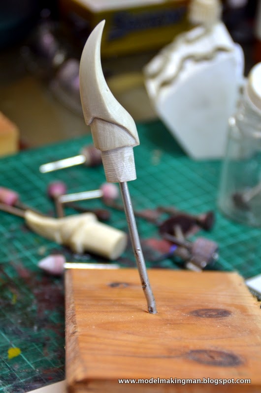
Now comes the fun part, modelling the head - get this right or get out of town. The above shows two heads, one in old resin on the left, the other in Apoxie Sculpt. The block of resin was, as I mentioned, old, and as such was full of air bubbles and soft (a lesson for me not to be too miserly and buy some new). I always knew that this head would have to be carved because the horn needed to be sharp. The lower features of the head would be added to a fully shaped, sharp, hard horn. To make it, I formed a suitably over sized block of the putty and ground it down on the sanding machine, to be finished off with the motor tool shown. I'm not sure how toxic the powder from this putty is (resin being quite nasty), but I use a respirator and mask when any extensive grinding is done.


There aren't many pictures of Typhus about. I've found five and these don't help a lot, which you can also say of the model. Its head is tiny and the detail is sort of hidden in the hollow of the torso piece. These are drawings gathered so that I could build up a picture of what exactly I was looking at and hoping to build.


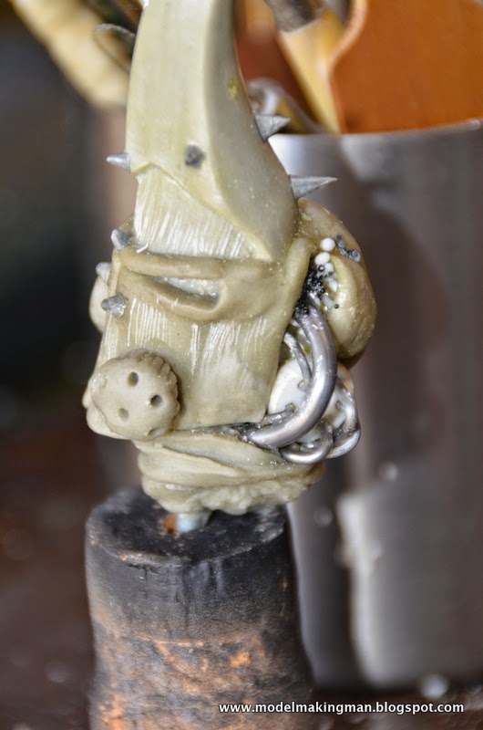


The details I found in this tiny little head astounded me. Really it is only a few mm long and yet there is all this stuff to make and define in the much larger scale I work in. I found that his head is a mask, and not only a mask but a half mask! It's complete on the right side and open with all manner of tubes etc, on the left. This was my first encounter with Typhus' "hive" bits, those round, raised and holey protuberances on the front. I think he really is just full of flies, the favoured insect of Nurgle, the chaos god of pestilence.
Materials you see used here include:  putty, solder for tubing, micro balls for pustules, a squashed lead sinker, spikes of sharpened hard plastic and white styrene plastic for connecting bits.
I kept the head on its wire support as the final form of the torso had a corresponding tube to receive it.


So here he is, in the hollow of his torso, looking to his left where he will be directing his rage, to be delivered by a dirty great scythe that men have named "Manreaper". 
The next entry will deal with this weapon and I might see about some legs as well.


Saturday, 6 April 2013

Giant Ork Part3


Remembering the sequence of this build is becoming more and more difficult as time goes by, so I will just present pertinent pic's as I realize what they mean. This, for instance, reminds me of the inevitable problem of a model's base. For one thing, it was really big and just manipulating it was a problem, so, having decided to create a 'gaming base', that is a circular form with a chamfered edge, I had to lock it down, hence the 3 wooden blocks. Once held, it still had to 'be' something. I decided to go with 'industrial wasteland' and the girder, rust and general rubbish appeared.
I had mentioned before, how the base had cost me half of what I earned in the sale of the model. This was a reference to the purchase of a sanding machine (belt plus disc), without which the necessary accurate chamfer could not have been achieved. Brother, has that machine paid for itself!


I think this pic is one of the best to show the tricky things modellers do to solve a problem. My problem with the whole model was that it was just too big to support itself. Once the huge arms were attached it leaned so far forward,( not that it overbalanced), but it put stress on the tips of the arms and hence, on the shoulder junctions. The solution lay in the fact that it was an Ork and therefore would not maintain its gear very well. Cables would inevitably come loose and never be fixed, so that thick loose wire with its red mate was really a 3mm, very solid connection to the base, supplied with a false frayed tail. The junction of stabiliser and base was hidden under more industrial debris. Now the model had a balance between its forward lean and the holdfast wire at its back.


This and the following two, show some of the detail on the backpack of the model. Things to note are: the use of lead sheet as corner pieces, many bolts/rivets sliced from Evergreen rod, hand made hex bolts, 'welds' made with Kneadit on pipe joints, extra bits of random plastic tacked on with holes in them, bits of other kits stuck here and there, drilled out and joined double holes,

 
 (contin) the repeated use of solder either naked or wrapped, as leads and cables, lots of carved Ork glyphs, those bits of plastic you get left over when a hole is punched in a sheet, tubes used as pipes, hydraulic rams or as cylinders, black rubber 'O' rings to seal a piston ram, nice round headed rivets made by heating rod in a flame, sliced plastic beads to complete a larger cylinder, tan kit parts from a tank,


(contin) tubes cut at angles to create joins, recessed dials with transparent coloured windows, more plastic beads as cylinder ends, bundled wires, reinforced pipe joints, mesh grills, etc, etc, etc.


Here is the model in its entirety with a 30cm ruler as size gauge. At this stage the support wire was probably not even thought of, but it does show the method I used to join the arms to the body. It needed to be robust and the common method of a single pin (used to effect in small figures) would not do here. The heavy wire, (3mm), was used in a triple prong that spread the forces across the shoulder plate and so long as the holes were drilled straight, it would do the job.


Painting has begun with a black undercoat. The shoulders had been drilled out in many places to accommodate bundles of wires that the Ork would use to control its limbs, but I used them to conceal the physical junction of the arms to the body.


I really like this picture of his face and wish that Orks were really black, but we all know that they are green and it's not easy---- to be around green, in this case.
 
 
Base colour coats have been applied, all the metal parts done in Boltmetal. This pic shows the shoulder connective tubes which will hold the bundles of wires.


Those connections of wires can be seen here but I cannot describe what a painful process it was to get them there. I just remembered now as I saw these pictures. Isn't the mind a wonderful thing, that it can completely blank out experiences that we really don't want to revisit? Stuffing wires into an Ork's armpit for one.
 Do Orks have mothers? I'm not sure anything could love this dial, but there it is, beady eyed and vicious, ready to create mayhem and crack many a mirror.


The job completed! But there is an addition to the story----- a small (28mm) version of the big guy. As this was a commission, I would have nothing of it except the photos, so I decided to build me a little'un.


And here he is ! Thus ends the saga of the Giant Ork Mek, a job I never thought I'd replicate,  but then I started Korpus Festerheart.........fool!


Tuesday, 12 March 2013

Giant Ork mechanicals Part 2


To make the ork's mechanical arms, a number of Evergreen styrene extrusions came in handy. Tubes, up to 1cm diameter, L shapes, I beams and many others were used, but anything bigger had to be scratch built, so other 'stuff' was put to good use. Standard styrene of various thicknesses was the mainstay of these builds, but you will recognise other bits all over the place. As this model is at least 5 years old, I really can't remember what I used or what was difficult, but it goes without saying that all problems can be overcome with a little ingenuity or a radical change of plan - nothing is set in stone.

You can see above that the large blades of the arm are chamfered to produce the cutting edge. This was done with the most valuable tool of all, the hobby knife used as a scraper, not a cutter. The other thing I like doing is making hex head bolts from punched plugs of styrene, the less accurate the better, ork mechanics remember.


 These three photos give a good idea of the way I go about dressing up the arms. Colours other than the stark white of the styrene (unless I used black sheet) give the materials used. Greenstuff, to create a welded look next to a major plate, strips of dark grey sheet lead for strapping cylinders in place, orange  and tan looking plastic pieces, probably from an old tank model, shiny wire wrapped to become some sort of major connection etc, etc.
In this sort of build you really cannot have too much textural "gizmology", the thing you can't have is a large blank surface, so fill it up!
To show the extent to which I go in re-using materials, have a look at the pieces of styrene that had circles punched out of them. Normally this is 'waste', and is binned, but with the circular shape on the edge they make perfect bolt surrounds.


Work continued on the ork body and I had changed to a fresh batch of Sculpey, flesh coloured even. The new stuff was much easier to work with and the sculpt really started to move along. Here you can see the use of thick lead solder as a connector to the belly armour. 


This is the completed right arm, together with shoulder girdle adorned with pyramidal shaped spikes. These spikes were actually quite difficult to make, seeing as they were very visible and needed to be roughly the same size. I seem to remember having to make a mould using the blue two part silicon system by Gedeo called Siligum. It mixes quickly as two solids and the resulting compound, once cured, is quite firm, so can take the forced-in Sculpy to make a plethora of spikes.


The work has begun on the back pack and shoulder support features. Large pieces of styrene were used and sometimes to get the correct thickness, they had to be laminated, glued and clamped. That big cylinder was a model in itself (as were many of the individual bits ) but I remember it to have been a particular trial, due to the curved ends. Those inset dials were a complex job of 'layering' in that they  needed to be deeper than the surface but also, in having them covered, they had to be pre-painted and hence, protected from all the surrounding work. Do you like the three blue beads?


To finish off this entry, I will show you my favourite bit of the whole build- the right foot! Starting as only as a  connective element to the base board, it developed into a strong ork boot, (a good match for its partner), then developed into a braced and electrified member attached to its own power source on the belt above. The reference I had to build this, was very sketchy to say the least, and I'm incredibly pleased that it turned out at all.


Here he is in a sort of totality, at a solid slump forward (which would be a real problem to overcome before the end). 
By the way, have you figured out how the base was made? Whatever money I made on the sale of this guy, that base cost me at least half.